Fiber Polarity in MPO/Cassette Systems Nat Bassett, RCDD/NTS/DCDC
In the network cabling industry there are several guides that explain individual Polarity Methods but none that address why such strategies are needed or the common principles upon which they are all based. Thi is unfortunate since understanding the “whys” behind the Methods is fundamental to being able to address the complex challenges that arise when engineering, installing and troubleshooting multi-strand fiber systems.
This paper fills that void by first identifying exactly what problems the various Polarity Methods are designed to solve and then describing in simple terms the four main versions that are currently in use.
Polarity in Two Strand Fiber Circuits
To understand why polarity strategies are necessary it is useful to start with the basic, two-strand systems where polarity principles were first established.
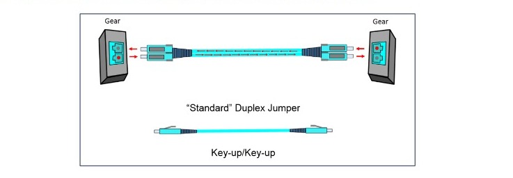
In a typical two-strand LC fiber transceiver, the left side of the transceiver sends while the right side receives
Connecting two pieces of active gear collocated in a shared space can be as easy as plugging them together with a “standard” key-up/key-up, duplex LC patch cord as shown here.
This simple direct connection automatically aligns polarity so the “send” (TX) on the left correctly maps to the “receive” (RX) on the right and vice versa. If all fiber connections were this straightforward, there would be no need for polarity rules.
The A to B Rule
Where rules become necessary is when these simple connections grow into the multi-segment fiber links typically found in large buildings and data centers. The rule used to maintain correct polarity in these situations is called the “A to B” rule.
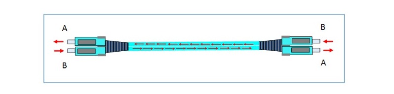
Using the A to B rule, the end of the fiber where the light comes out is designated as end “A”, and where itgoes in is designated as end “B”
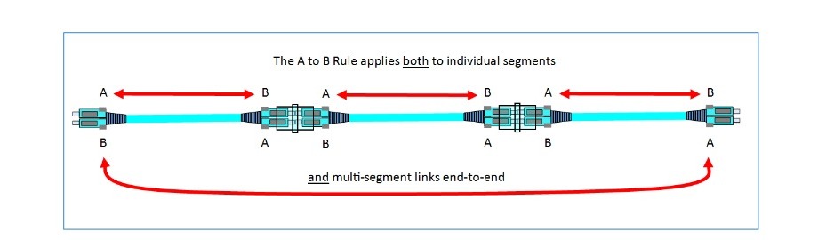
Following the rule, a fiber end “A” must connect to an end “B” at each connection point in a multi-segment link. Notice this rule not only applies to individual segments, but the entire link from end to end as well.
In addition, the “A” end of a given fiber must ultimately map to the “B” end on the other end, no matter how many segments it goes through. If it does not the polarity will be wrong, and the link will not work since the light will not be entering the correct side of each transceiver.
This is relevant because the A to B rule does not just apply to two strand links, it also applies when those links are aggregated within MPO-based cassette systems. Simply put, “A” on one end must always connect to “B” on the other end. This is an essential rule for all such fiber systems.
Cassettes and the “New” Problem of Port Position
With the two-strand methodology so well established one cannot help but wonder why 12-strand MPO links seem so complicated. Do we really need Polarity Methods to make these systems work? The short answer is “yes” and port positioning is the main reason why.
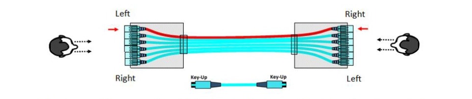
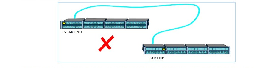
To get a feel for the importance of port positioning one must take the perspective of a technician looking at the cassette at each end of a 12-strand link
If six, two-strand links are simply bundled together and placed in cassettes with no other strategy applied, the duplex ports will not align to the same position at each end of the link. For instance, looking at the graphic above you see the left-most port at one end maps to the right-most port on the other end. Every 3 other duplex port will likewise map to its mirror equivalent on the other side. In this scenario the A to B polarity on each duplex link is correct but the port position is not.
To be easy to administer, a connection to duplex port 1 on one side must connect to duplex port 1 on the other side. Otherwise the connections appear in different places at the near and far end patch fields which is completely non-intuitive and unworkable.
To sum it up, the various Polarity Methods may be understood as different approaches to correct the problem of port position while preserving the correct “A to B” polarity in individual 2-strand fiber circuits.
Method A
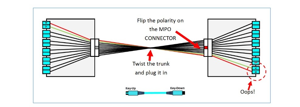
The first approach to fixing port position is to take the MPO trunk and put the key on the opposite side of the MPO connector at one end. In other words, make the key-up/key-up trunk into a key-up/key-down trunk. The trunk assembly is then simply twisted over and plugged back into the cassette. This change makes the leftmost port on one end connect correctly to the leftmost port on the other end – a much easier system to administer
If you look closer however, you might notice a new issue. See how fiber end “B” now connects to “B” and “A” connects to “A” at either end? This violates the A to B rule.
This happened because while making the trunk key-up/key-down does correct the port position, it also transposes the fiber pairs on each two-strand port. This issue always arises in systems that use key-up/key- down trunks. To repair polarity, we must now introduce what TIA refers to as a “pair-wise flip” on each pair of fiber strands somewhere in the system.
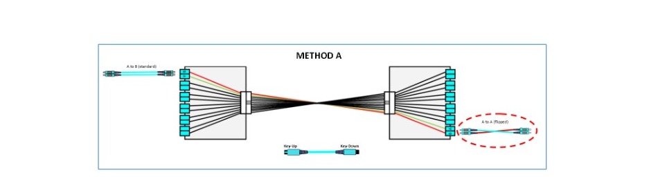
The easiest way to introduce the flip is to use a standard “A to B” patch cord on one end, and a flipped, “A to A” patch cord on the other end to tweak the pair polarity back into place.
While this practical approach does yield a workable system, it also forces the system owner to keep track of two different types of LC patch cords. Fortunately for the owner who does not to want to stock two cords, this corrective pair-wise flip can be also be done elsewhere in the system, making it possible to use only standard patch cords. The first of these alternative approaches is called “Modified Method A”.
Modified Method A
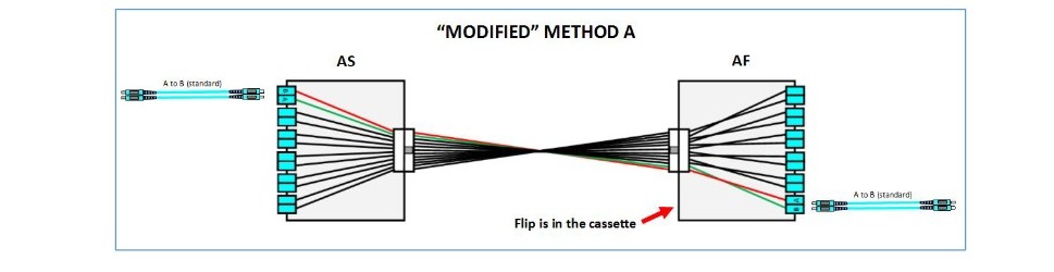
In the modified version of Method A, we still use a key-up/key-down trunk but now place the pair-wise flip correction inside one of the cassettes rather than using a flipped patch cord
The system owner can now use the same jumpers on both sides with the trade-off being there are now two types of cassettes – an “A Standard” (AS) cassette, and an “A Flipped” (AF) cassette. But since patch cords move a lot while cassettes are relatively static, Modified Method A is a solution preferred by many users. With Modified Method A they can install the cassettes once and not have to think about polarity every time a new patch cord is added to the system.
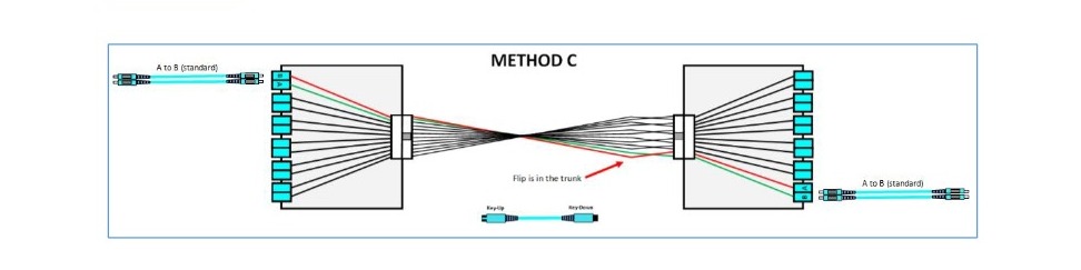
Method C
To take this concept even further, it is also possible to correct the pair-wise flip inside the trunk itself. Here the trunk is still key-up/key-down just as in Method A but now the pair flip correction is done inside the trunk as shown below
Method C, however, presents some difficulties when designing multi-segment MPO links and has inherent limitations when migrating to parallel optics systems. For these reasons it has never gained much traction in the industry.
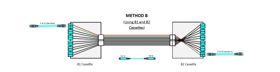
Method B
Method B uses a two-different-cassette configuration like Modified Method A only now the cassettes are referred to as “B1” and “B2”. Since the Method B trunk is key-up/key-up there is no need for a pair-wise flip in the system so standard patch cords can be used at each end.
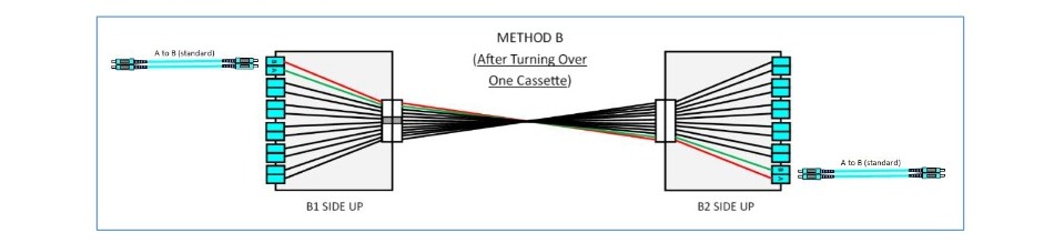
There are two ways to deploy Method B. The first and simplest way is to physically turn one cassette over, installing it “upside down”. This corrects the port position without altering polarity since the trunk configuration remains logically key-up/key-up.
Keep in mind the ability to mount a cassette in the turned-over position requires a system that is designed to allow cassettes to be installed either face up or face down. The advantage to this approach is that only one cassette type is needed.
The disadvantage to turning a cassette over like this, is that the LC latching tabs (key) will point up on one end and down on the other. Whether or not this is acceptable is a strictly matter of taste. Many end users don’t mind this. Others think it looks wrong, like one end of the system is installed incorrectly.
The second way of deploying Method B is for those users who insist the LC latch be oriented up on both ends. Here we use a “true” B2 cassette where the port position changes are done within one of the cassettes as shown below
Whichever deployment approach is used, Method B has emerged as one of the most popular cassette methods to date. It scales easily and is compatible with 8-strand parallel optics protocols. There is however another Polarity Method that is coming on strong that may challenge Method B for the top spot.
The Universal Polarity Method
The “Universal Polarity Method” has had limited acceptance since until recently it was a proprietary system offered by only one manufacturer. Such proprietary approaches are often avoided by system users not wishing to be “locked-in” to one supplier. Due to recent developments however, this method can now be offered by any manufacturer.
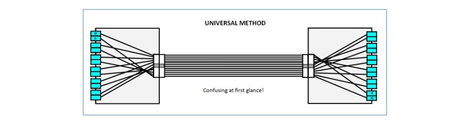
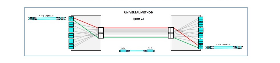
The Universal Method allows for the use of one cassette type and requires only standard A to B patch cords. How it accomplishes this can be a little hard to understand at first.
However, if we highlight the fiber between each of the first three duplex ports the strategy becomes clear.
In the Universal Method the fibers connecting port 1 route along the outermost strands of a key-up/key-up trunk, and then map directly into port 1 on the opposite end. Since the trunk is key-up/key-up, there is no need for a pair-wise flip in the system.
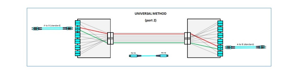
The second port connects similarly by using the next two fibers-in on the trunk.
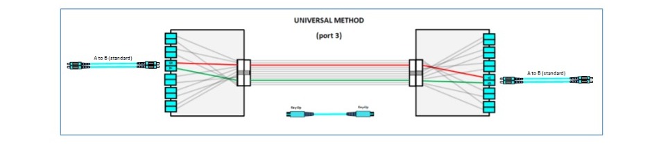
As we move down to port 3, the signal follows along the next two fibers-in, and the pattern becomes clear. The Universal Method is an ingenious way to handle the challenges of polarity and port position. Now that it can be sourced from multiple manufacturers, we are likely to see a greater use of it moving forward.
Conclusion
This paper explains why Polarity Methods are necessary and how the four main Polarity Methods work. Related topics not addressed include complex multi-segment links, MPO harnesses, interconnects, parallel optics, QSFP transmission, dark fiber mitigation, tap cassettes, and a myriad of other polarity spin-off topics that are beyond the scope of this paper.
Should any questions arise regarding fiber distribution systems, contact your local Panduit representative. Panduit employs field-based systems engineers to provide in-person, hands-on assistance for your fiber projects. In addition, Panduit maintains a world-class fiber research lab and a Fiber Division staffed with product engineers to help evaluate and support your fiber system challenges.